DC & Stepper Motors
The driving technology base base for both DC & Stepper Motors (Rotating Electric Motor) is electrical energy that is converted into rotating mechanical energy.
This page describes the different DC & Stepper Motors found in our Motion Control products.
DC Motor
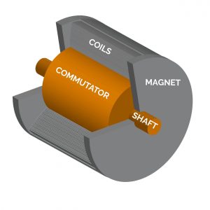
A DC (Direct Current) Motor produces electrical energy as the stationary stator (magnetic field) interacts with the rotating rotor (conductors loops). The Electrical energy is transformed into mechanical energy that enables continuous movement of the stage axis (which is a result of the Lorentz Force effect).
DC motors provide operational advantages over other drive types as they are:
- Good dynamic performance with a large control range
- Vibration-free operation
- Low heat dissipation
- Large velocity range
- Low vibration at high position resolution
- High torques at low velocity
- Robust and long lifetime – Suitable for industrial applications
DC Motors Types
We offer two types of DC Motors
- Brushless Motor – Produces a magnetic field by having permanent magnets attached to it and the commutation is electronically. Brushless Motors uses so called “Hall effect” switches in the stator. This produces the required stator field rotational sequence but they have better torque/speed characteristics, are more efficient and have a longer operating life than equivalent brushed types.
- Servo Motor – In the most basic sense a brushed DC motor with positional feedback control connected to the rotor shaft. A brushed DC motor has a magnetic field that produced by either a wound stator field winding or by permanent magnets as the electrical current passes through a commutator and carbon brush assembly, hence the term “Brushed”.
How a DC motor operates
The most simplified version a DC motors operates with resistor, inductance, and voltage source which results in a motor voltage as per the law of induction.
With an induced voltage that counteracts the motion (back-EMF) the force acts proportional to the rotational speed. When reaching the equilibrium between the back-EMF and the motor voltage maximum rotational speed is achieved. For DC motors, the voltage drop over the inductance can be neglected which results in rotational speed and a proportionality of voltage where the sign of the voltage determines the direction of rotation:
[𝑈 = 𝑅𝐼 + 𝑘𝜙2𝜋𝑛]
A combination of the torque and current results in the decrease of rotational speed under load that is proportional to the torque.
Position Control
To control the motion of a stage, the DC-motor requires position encoders. This is either through incremental or absolute encoders and is operated by either an open or closed servo loop system.
Open Loop – The input signal is passed through the motor which produces an output signal that is further discarded. This means you do not receive any feedback from your input. For a motor that uses a closed loop on the other hand, the encoder signals is returned back and enables a high position resolution, large dynamic range and constant feed of the motor. This in effect allows DC servo motors to control position, torque and velocity. Note that when the motor tries to keep its position when using closed servo loop it results in position jitter.
Closed Loop – A normal closed loop servo motor will use a rotary encoder for the motor shaft controlling the speed and an additional linear encoder on the motion platform for position control. Using a dual loop controller both the velocity and position control can be deployed at the same time by using the linear encoder. This would be advantageous for examples when there is low resolution as a result of the minimum incremental motion from the rotary encoder. There is a disadvantage which occurs as the linear encoder registered the oscillations of the motion platform to a higher degree than the rotary encoder on the motor shaft. This causes the bandwidth to be reduced of the velocity control loop.
Continues vs. Short Term Operation
From the torque speed characteristic curve, we identify the nominal operating point that is the intersection between the torque speed, continuous operation and short term operation.
You can identify a powerful motor by the flat characteristic curve as rotational speed is not affected by load changes. To maintain the gradient when shifting the torque speed characteristic curve up we need to both increase idle speed as well as a utilize a higher starting torque. This will in effect require a thicker copper wire for the DC-motors winding or an increase in voltage during operations. Continuous operations is normally only tolerated with limited torque speed.
The short-term operations highest acceptable overload is limited by the copper wires maximum temperate. Note that very high currents might cause the permanent magnets of the DC-motor to be permanently de-magnatized. Furthermore, the mounting position, ambient pressure (vaacum), convection and more could also restrict the use of the the permanent magnet. For short term operations the permissible residence time is one to three seconds and signified by the extent of the overload and the thermal time constant of the winding, as shown by the following type example:
[fig 5]
Higher loads lead to increased operational temperature as we get an increased motor loss due to the proportionality of current and torque. We can estimate the temperature changes by multiplying the thermal resistance by the current heat loss from the corresponding motor data sheet. Would you need to operate the motor at its thermal limits, a closer investigation is required as it is limited thermally by the maximum winding temperature of the DC-motor as well as the external surrounding temperature.
DC motor with Active Drive
To achieve higher velocities for DC motors that have a rated power that exceeds the controller’s output power, Physik Instrumente developed the ActiveDrive technology.
This technology is based on an amplifier that is incorporated within a shield case. The integrated amplifier (supported by an additional power adapter to optimize heat dissipation to maintain precision) is then triggered via a Pulse Width Modulation (PWM) and controls the motor power by the ratio of on/off-duration as depicted below:

Brushless DC Motor and Synchronous Servo Motor
With a brushless commutation both Brushless Direct Current (BLDC) and Synchronous Servo Motor (SSVM) offers several advantages over a brush DC motor. The following advantages are usually preferred for industrial applications:
- Lifetime – Regular DC motors are limited by the bearings which will only last several ten thousand hours.
- Larger torque/motor size ratio – DC Motors with a brushless design are smaller, lighter and low in maintenance as well as being more efficient while still providing the same performance.
- As a result of the electronic commutation a brushless DC motor permits high dynamics at low temperatures with few vibration
Benefits
- Good dyamics over a large speed range
- Low heat generation
- Vibration free & smooth operation
Limitations
- Only applicable to application in vaacum up to 10-6 Anything lower than this will not be able to support the humidity needed for the carbon brushes to communicate with the controller.
- The brushes of the motor release carbon dust which can be problematic for use in vacuum, clean rooms and optical applications.
Motor Design
The brushless motor design resembles the one of a permanent-magnetic synchronous machine and the terms BLDC and SSVM are often used interchangeably. However, BLDC emphasizes the brushless commutation while the term SSVM focuses on the rotor movement synchronous to the rotation magnetic field and the two are occasionally seprated based on the commutation control type being either block or sinusoidal.
For this reason BLDC motors are commonly referred to as SSVM when used for industrial applications operated at a low voltage range.
Stepper Motor
Stepper motors take discrete positions within one revolution. Because these steps have a constant distance, a position may be commanded using the number of steps without the need for a position sensor. Normally, there are 200 to 500 full steps in each revolution. The actual achievable step size is determined by the stepper motor control, and depending on the version it electronically interpolates up to several thousand microsteps between the full steps.
Stepper Motors are very stable when holding a position, particularly full steps. However, current must be continually applied to stepper motors that do not have a a self-locking gearhead.
Motor Design
Stepper motors heat up during (continuous) operation and this must be taken into account when designing a system.
Stepper motors take discrete positions within one revolution. Because these steps have a constant distance, a position may be commanded using the number of steps without the need for a position sensor. Normally, there are 200 to 500 full steps in each revolution. The actual achievable step size is deter- mined by the stepper motor control, which, depending on the version, electronically interpolates up to several thousand microsteps between the full steps.
When holding a position, stepper motors are very stable, particular the full steps. For this purpose, current must be continually applied to stepper motors without a self-locking gearhead.
Controlling a Stepper Motor Stage – System Management Controller (SMC)
A Stepper Motor that utilizes the control technology of the System Management Controller (SMC) can benefit from the following:
- High position resolution, smooth feed, and a large dynamic range of velocity and acceleration
- High efficiency avoids the motor to over heat
- Position resolution down to the nanometer range, with high-resolution amplifiers based on a 32-bit processor
- Uniform feed velocities of less than 1 μm/s can be achieved in combination with high-precision mechanical systems.
- A sin2 profile can be chosen to achieve smooth acceleration and deceleration phases, in addition to a linear acceleration profile.
- If stable long-term positioning is required, SMC stepper motor controllers also evaluate position measurement systems with precise control.
- Set a very accurate and infinitely position without limitation by bit-depending digital transformation through the processing of an analog 1 V peak-to-peak value.
System Management Controllers are available in different versions, from a one-channel compact unit to a 19″ housing used for multi-axis control .
Acurrate Positioning with System Management Controller
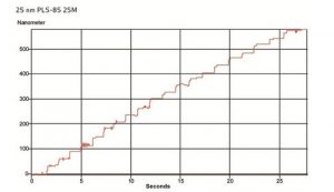
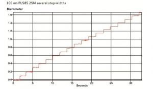
The graph above compares the commanding of a two-phase stepper motor without additional position feedback at stepps with both 25 nm (Fig. 1) and 100 nm (Fig. 2). There are more variations in the individual steps at 25 nm increments (average deviations are only ±5 nm) compared to 100 nm which achieve great precision.
Correcting the Position Error in the Controller
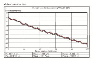
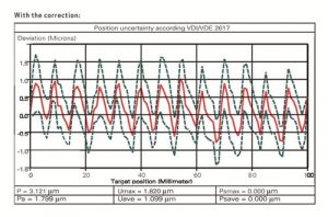
The positioning accuracy that can be achieved is normally limited by the quality of the guides and the drive train. For example, a nonlinearity of the spindle pitch causes a deviation from the commanded position. In some applications it is important to improve the absolute positioning accuracy while bidirectional repeatability is less relevant. The error correction in the System Management Controller saves the measured deviation and then corrects the target position correspondingly.
The deviation in position of 32 µm between target and actual position over the travel range of 100 mm is shown in figure 5. The measurement includes both directions of motion and the average bidirectional repeatability is 1.78 µm.
The deviation is considerably smaller, only about ±1.5 µm when using correction as per the result shown in figure 6. Repeatability can be improved further by means of position control.
Position Control
If the analog output signal of a high-resolution sensor is used for processing the position behavior for small steps can be improved with position control. System Management Controllers can process sensor resolutions down to 2 nm. The position resolution then only depends on the sensor. Environmental effects should not be neglected as variations in ambient temperature of only 0.01 °C already cause thermally induced expansion of the stage by approx. 10 nm. To mitigate this stages with a granite base and corresponding high-resolution linear encoders such as ultra-precision stages or specific developments are used.
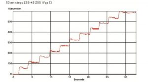
The measured minimum incremental motion of an LS-110 stage with linear encoder is shown in figure 3. The precisely separated steps of a 50 nm resolution can be clearly and even changes in load will not affect this accuracy.
Velocity is a decisive parameter for selecting a positioning system, which can probe a major challenge for both DC & Stepper Motors. Some applications require a particularly slow and even feed motion, but this usually relates to the maximum achievable velocity. Therefore the velocity control of System Management Controllers guarantees an excellent stability of the stage velocity in the range of << 1 µm/s.
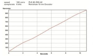
The results of an integrated linear encoder with 10 nm resolution is depicted in figure 4. The motion of this stage is very even with the velocity set to 100 nm/s (which equates to a feed of 360 µm/h or approx. 10 mm/d). The individual steps shown here are due to the interferometer resolution of 5 nm.
Is This The Right Drive Concept For You?
There is no single solution that supports the ideal drive concept in positioning applications. It is therefore important to understand the numerous parameters that effect your application. The travel range needed or the required stiffness of the system, as well as the power supply available, would all need to be considered. Additionally, the desired control behavior as well as the installation space available and potential safety requirements, including standards and the costs has to be taken into consideration.
Adapting to our Customer Needs
For us it is importaint to understand what your application need is. Based on this togheter with Physik Instrumente we adapt all the magnetic drives system components to meet your specific requirements.
Together with our suppliers know-how in guiding systems, control technology, and nanometrology sensor systems, we can meet the applications specific requirements you have. It therefore virtually makes no difference regarding which principle your positioning system operates.
Contact us to find out more about DC & Stepper Motors. We are more than happy to help you find the right solution and provide a tailor-made positioning solution.
Wyślij zapytanie
* This page is a rendition from our Supplier, Physik Insturmente GmbH, Rotating Electric Motor page.

